[ad_1]
Fuel cell powered vehicles are becoming an essential part of the electromobility transformation. The core component of the powertrain is the electrochemical reactor, known as the fuel cell stack. Commissioning is carried out on test benches where all essential functions are tested. Afterwards, the requirements for the entire fuel cell-electric drive are checked with a system validation. All basic data of the entire system need to be measured with high precision for the performance parameters can be verified.
Background
The fuel cell stack is a series of individual fuel cells, where the energy from the chemical reaction of continuously supplied hydrogen and atmospheric oxygen is converted into electrical energy in “cold combustion”. This requires a precise operating system that feeds hydrogen, atmospheric oxygen and moisture to the stack. The stack is temperature controlled by a cooling system. The fuel cell current is a measure of the current density occurring in the stack. Depending on the characteristics of the fuel cell, the output current leads to an actual fuel cell stack voltage. The current and voltage must be measured synchronously. This stack voltage is composed of the number of fuel cells in the stack. Without power output, the fuel cell stack has a certain open circuit voltage which is also controlled in all test runs.
The fuel cell-electric drive is usually a complete subsystem of the vehicle provided by a supplier. The overall vehicle performance and dynamics is the result of the electric drive combined with the other powertrain subsystems. The characteristics, functions and properties of the fuel cell-electric drive are verified on test benches up to production release through various tests. The energy from the fuel cell stack is delivered to the DC/DC converter, which serves all other high-voltage components of the vehicle. They are interconnected via the high-voltage vehicle electrical system. The power electronics of the DC/DC converter also contain important functions, such as setting the stack setpoint current for the respective operating mode. The DC/DC converter also contains a boost converter, for example to 700 V for the drivetrain (inverter and e-motor) and the traction battery.
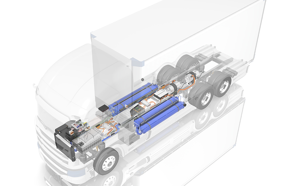
Fuel cell electric vehicles usually have diverse operating modes, depending on the selected operating strategy and desired driving dynamics. The fuel cell stack provides the necessary electrical energy for both the traction drive and battery charging.
SEE ALSO: CSM’s free webinar at the Charged Virtual Conference:
Functional Test And Measurement Of Fuel Cell Electric Drive System
Challenge
The functional tests cover all operating functions such as the cooling circuit, cooling control, heating, hydrogen (anode) paths, air (cathode) paths, high-voltage electrical circuits, sensor technology and fuel cell control unit. Therefore, high-precision measurement of a wide variety of physical parameters is required for the functional testing and validation of fuel cell drive systems. In addition to temperatures, volumetric flows, humidity and pressures, measurements of currents and voltages in the high-voltage circuits are necessary. From these, the delivered energy, power and efficiency are calculated.
The individual sub-systems for hydrogen, air and cooling circuits are individually applied and commissioned. A defined start-up process is carried out to start the fuel cell system. After that, the specific system functions are tested: Cold start behavior, warm-up phase duration, operating points, thermal management or the cooling circuits. A functional test proves whether the system behaves as it should, for example whether all control parameters are set correctly.
With validation, the system requirements such as performance parameters, reaction speed to load changes or service life are proven with vehicle tests and endurance runs.
Current, voltage and power measurements are used to check correct operation in these various operating phases. For example, the characteristic curve of the power during the warm-up phase, for start-up, load changes, partial load and peak load as well as various other distinctive operating points.
The voltage ripple occurring in the High Voltage DC circuit must be checked, because limits are defined for magnitude and slope. The allowed ripple current load, for example, at peak load must also be verified.
With the measurement of currents, voltages and powers in the high-voltage paths, all transient processes are also checked. For example, when the fuel cell stack is switched on or when subsystems such as the air compressor or the cooling system are switched on. Here, the current and voltage curves must be measured at a high sampling rate of 1 MS/s in order to caputre voltage dips, amplitude slopes, ripple magnitudes and interfering subharmonic frequency components.
Ultimately, the specified efficiency curves of the fuel cell-electric drive are determined. The efficiency is the energy delivered in relation to the hydrogen consumed. It depends on the load point and the optimal supply of the different media: hydrogen, atmospheric oxygen, humidity and cooling. A non-optimal supply, for example of stack humidification, leads to a drop in stack voltage.
Accurate measurement and analysis of current, voltage, power and efficiency verify and prove all system-relevant performance parameters of the fuel cell electric drive.
Measurement solution
The Vector CSM E-Mobility Measurement System (www.csm.de/ev-ems) includes all necessary hardware and software to perform these required measurements and analyses.
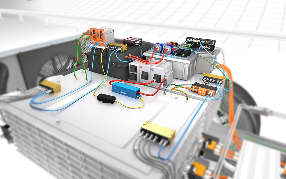
For direct current, voltage, and power measurement, a High-voltage Breakout Module 1.2 (www.csm.de/ev-bm) is inserted in the HV+ and HV- cables between the DC/DC converter and the battery. Additional Breakout Modules (HV BM 1.1) measure the currents of the air compressor and the cooling system. Simple current measurement can be performed via CAN at sample rates of, 1 kHz, for example. For fast measurements of current, voltage and power up to sampling rates of 1000 kHz can be used, via EtherCAT® (ECAT) bus. For current measurements inside auxiliaries, CSM LEM sensor packages can be used, to be connected via analog-to-digital modules (AD4 MiniModules) also on the ECAT bus.
The AD4 ECAT MiniModules are used to time-synchronize the measurement of all other voltages required for verification.

The measured values from CSM’s ECAT modules (HV BM’s and AD4’s) are sent to the XCP-Gateway, which converts the data into the XCP-on-Ethernet protocol and transmitted to the data acquisition computer.
At the stack supply, all important physical parameters are measured with additional CSM low and high voltage modules with lower sampling rates on a CAN bus. The sensors for measuring volume flows, pressure and humidity are connected to conventional and high-voltage safe CAN MiniModules (www.csm.de/ev-hvmm). Temperatures are measured at high-voltage critical points via HV TH8 evo modules. THMM 16 MiniModules are used at other measurement points.
Benefits
With the conventional and high-voltage measurement modules from CSM, the test bench and vehicle can be equipped to meet the specific measurement requirements. High-voltage safe modules are used where measurements points are in high-voltage environment. EtherCAT measurement modules allow a high sampling rate to assure that high-speed transient data is not missed.
High voltage breakout modules allow direct measurement of high currents and voltages with calculation of instantaneous power in the HV cables. Measurement data are sent via traditional CAN, or via EtherCAT for fast measurements with a sampling rate up to 1 MS/s.
CSM LEM sensor packages are used for current measurements at installations with space constraints. These current transformers are connected via a CSM ADMM4 measuring module, which also performs the simultaneous voltage measurement.
The integration into a test bench software like ETAS INCA for fast measurement is very easy: The software add-ons “CSM INCA AddOn ETH” allows an easy integration of the CSM measurement modules into the INCA measurement and analysis software from ETAS. The configuration is easily done via a customized user interface.
For accurate power analysis, the Vector software vMeasure exp with the eMobility Analyzer is ideal.
To learn more, register for CSM’s free webinar at the Charged Virtual Conference:
Functional Test And Measurement Of Fuel Cell Electric Drive System
[ad_2]
Source link
