[ad_1]
By: Peter Klaerner, senior manager for Wedge Bond Systems Engineering,
Kulicke & Soffa
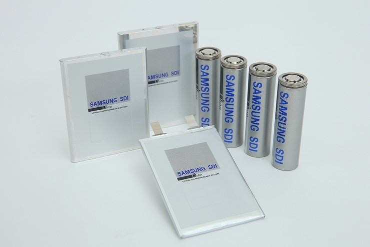
Wire and ribbon bonding have traditionally been the methods of choice for creating reliable interconnects in the electronics industry. The progress in electric vehicle production has created the need for better, more reliable interconnects that can be scaled to high-volume manufacturing. It is no surprise therefore that leading automotive manufacturers in the electric vehicle space have turned to wire bonding for their interconnect needs. Such interconnects must be able to handle extreme temperature ranges in addition to shock and vibration conditions over increasingly longer lifetimes. There are several areas of application for interconnects in electric cars. Some of the applications include: battery cell-to-cell connections; battery cell-to-busbar connections; battery management system (BMS) interconnects; and power module interconnects in the electric car drive train.
A leading electric manufacturer claims that their previous battery generation was designed to last up to 500,000 miles of service and their current generation of batteries is targeted to last up to 1,000,000 miles of service. While only limited real-world data is available due to the somewhat nascent proliferation of electric vehicles, long-term data available so far has shown that those claims may be credible. In addition to the battery chemistry that holds the electric charge, the interconnect elements between battery cells and sections are components that see stress over the product lifetime. Between the multiple interconnect methods being used in battery interconnects (see Figure 1), wire bonding is the method with the most real-world data available demonstrating its reliability.

What are the advantages of wire bonding making it a preferred method of interconnect formation in the electric car industry?
Advantages
Quasi room-temperature process
The wedge wire bonding processes do not require external thermal energy. In contrast to other methods like resistance welding, soldering or laser welding, the substrate to be bonded does not need to be heated nor does the wedge bond process induce heating. During the wedge bonding process, very localized heating occurs only for a very short time due to the micro-friction occurring between the bond interfaces. This is a great advantage when forming interconnects in heat sensitive battery cells or integrated circuits.
Flexibility
Wire interconnects can span considerable distances and height differences between interconnect points. Product iterations leading to changes in both distances or heights can be easily accommodated with a simple software adjustment – no new costly hardware has to be manufactured. This flexibility also enables different product configurations to be processed on the same bonder equipment requiring only a product-specific process program to be loaded.
Ambient and product-related thermal stresses can be accommodated with stress relief loops between the interconnect points. Wire interconnect processes have been developed between 18-micron wire diameter on the low side, and up to 600-micron wire diameter on the high side. Suitable wire sizes can be chosen to match resistance and conductivity requirements. For fine-tuning of exact resistivity or impedance, as is sometimes required in electronics processes, the loop shape can be dynamically adapted to changes in bond locations for desired resistivity or impedance matching. Ribbon bonding processes – typically used to enable higher current transfer due to their higher cross sections – have also been developed to cover a large range of sizes.
This flexibility enables cost savings during the pre-production phase, and also during the production phase.
In-process monitoring
During the wire bond process, a number of electrical and mechanical signals are being captured in real-time. While the bond process is taking place, this allows for an immediate evaluation of the bond conditions and a judgment of bond quality. With modern data analysis tools, it is possible to classify and match signatures of common failure modes such as contamination or misplaced bonds and store questionable bonds for later post-bond review. Connecting and storing the bond data with product serial codes it is possible to have full traceability back to each individual bond.
Mechanical process assurance
Wire bonding offers the ability to perform a mechanical pull test in-situ. In this non-destructive test, a pre-defined pull force is applied to test the bond strength after each bond is completed. Pull testing detects infant mortality failures of weak or non-stick bonds. Similar to the bond process data, pull test results are immediately available and can be stored for full traceability.
Ability to re-work
Wire bonding offers the ability to remove weak or failed wires on an individual wire level and attempt rework. The ability to rework offers a unique advantage compared to other interconnect methods which only have a singular chance of success.
Proven technology & reliability
Wire bonding as an electrical interconnect technology has been used since at least the 1960s and has continuously been improved. As explained earlier in this article, reliability in electronic components has been demonstrated, and more recent evidence confirms that wire bonding is suitable also for the extended shock and vibration demands placed on it for battery cell applicationsiii.
Established supply chain for both equipment and consumables
For large scale automotive production, a stable supply chain for both equipment and also consumables (such as bonding wire) is available with a global reach.
Fusing
As explained earlier, in a typical wire bond application the interconnect is designed to endure harsh environmental conditions. There is however a use-case in which there is a designed and desired failure point of the wire bond: when an un-intended overcurrent condition occurs. U.S. Patent No. 7,671,565, assigned to Tesla, Inc., described it as follows: “A system and method links batteries in parallel to conductors using wire bonds that act as fuses in the event of an overcurrent condition in a battery.” The wire bond can be specifically tuned to the required fusing characteristics by selecting a suitable wire size and loop length – both of which determine the resistivity of the interconnect.
Limitations
Of course, every process has some limitations. For wire bonding processes, exemplary limitations include:
Serial process of interconnection
Wire bonding is serial in nature in that each bond has to be formed sequentially. The only method to parallelize work involves multiple bond heads working on the same product at the same time. This adds complexity to the equipment and often limits flexibility. If a product is very repeatable in dimensions a multi-bond head approach can be executed. Such equipment has been used, for example, in solar cell interconnects where the bond locations are identical for each workpiece.
Contamination
Contamination at either bonding interface can greatly affect the bond integrity. This applies to organic materials such as hydrocarbons and non-organic materials such as oxidation and dust. Mild contamination may be addressed with selective bond parameters, while severe contamination typically requires a cleaning process. Particularly in the prototyping stage of battery development packs, it is not uncommon to deal with epoxy and other polymer residue caused for example by 3D printing during the wire bonding stage. While this contamination is caused by outside factors it can greatly influence the successful outcome of the wire bond process.
Requirement for a stable substrate surface
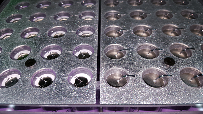
During the wire bonding process, ultrasonic energy is applied under pressure. The ultrasonic energy can cause harmonics that create resonance with the substrate surface. Excessive vibration of the substrate surface can negatively interact with the bond formation leading to weak or no-stick bonds. Therefore, a product design guideline used during the development process may include providing for a stable bond surface to ensure the highest success for the wire bond process. Particularly, battery cells tend to have a weak spot regarding vibration with the top cover of the battery cell having only support on its sides but none in the center (Figure 2).

Requirements for accurate placement location
While requirements for accurate placement location exist for all manufacturing processes, there are some unique challenges in the realm of battery cell interconnects. Such applications typically require that each cell be located at a known location so the bonder can accurately place each bond. Usually, this task is aided by using machine vision to locate reference marks on the product while each battery cell is located relative to that reference mark. It can be appreciated that as product dimensions grow there are stack-up tolerances during the battery module assembly process that negatively affect cell location accuracy. While a more precise assembly process can improve cell location accuracy it comes with the drawback of significantly higher product cost which affects each module. Another approach is to introduce more reference marks throughout the product to lessen the effect of stack-up tolerances across a large area by sub-dividing the area into small sections. Locating additional reference marks, however, requires additional find time prior to the wire bonding process, thereby increasing the overall cycle time. A brute force approach would be to use machine vision to locate each individual cell prior to bonding. This cell locating operation can be performed within the bonder but consumes an inordinate amount of time just for locating each cell. Another approach would be to locate each cell before the product enters the bonder with the drawback of having to transfer and synchronize a large amount of data between various systems. In summary, the solution to accurate cell placement comes at a significant cost and technical complexity.
Suitable metallurgy combinations
Wire bonding performs best with a number of suitable metallurgy combinations. Much research has been done to explore the bondability of various material combinations and a number of well-performing combinations have been identified. Typically mono-metallic bonds form the best connections such as aluminum-to-aluminum or copper-to-copper. While dissimilar metal combinations can be used the exact combination has to be evaluated as to bondability. It is advantageous if battery module and cell designers take the wire bonding process into consideration during the design cycle to achieve optimum production robustness. In cases where certain metallization is required that by itself wouldn’t lend itself well to bonding, coatings can be explored since wire bonding also works well on certain coated surfaces. This article only gives a very high level overview – Kulicke & Soffa will be happy to evaluate your specific application as to bondability.
Spreading beyond automotive
The success of wire bonding demonstrated in automotive battery applications has begun to spread to adjacent applications. Given the advantages wire bonding offers it is no wonder that wire bonding is now being utilized in applications such as energy storage, electric bikes, and motorcycles.
Kulicke & Soffa continues to provide innovative solution to create future possibilities.
Learn more of K&S’ wedge bond solutions:
https://www.kns.com/Products/Equipment/Wedge-Bonder
[ad_2]
Source link