[ad_1]
Supercharged solutions that provide for fast charging reliability, efficiency, and safety
The adoption of EVs will reduce pollution and help slow the effects of climate change. A significant impediment to broader EV adoption is both a public charging infrastructure that can support long-distance travel and chargers that can recharge an EV battery in a time that drivers will accept.
Currently, 300 kW chargers can recharge a battery in under 15 minutes. While the time is acceptable, the primary challenge for design engineers is protecting users from 300 kW.
Secondarily, designers must maximize efficiency to minimize power consumption and temperature rise. In addition, designs must perform reliably despite exposure to a wide range of environmental conditions.
Figure 1 shows several types of charging stations. North America classifies charging stations into “Levels,” while the European Union differentiates charging stations using “Modes.”. Organizations such as the Society of Automotive Engineers, the European Union automotive standards organization, and Asian countries like Japan and China are working to standardize charging stations.

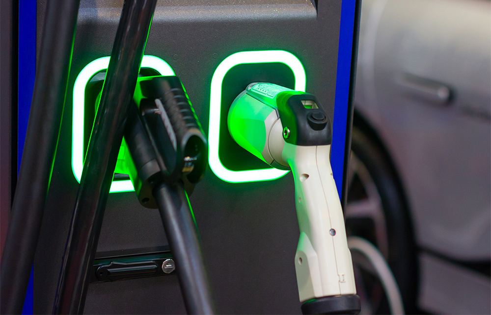
A DC Fast Charger (Figure 2) can charge an EV battery to 80% capacity in under 15 minutes. These chargers have power ratings up to 350 kW and can supply up to 500 A to a battery. To develop these chargers, designers must overcome the challenges of safety, efficiency, and reliability.

Methodologies for charger and user protection
Figures 3, 4, and 5 illustrate the circuits and components of a DC charger. A 350 kW charger requires a high voltage, high-current capacity AC input. To protect against overloads, use fast-acting, high-current fuses. Ensure the fuses have a current interrupting rating large enough to exceed the energy available from the AC line. Fuses can have ratings up to 200 kA.


Consider using a surge protector to absorb voltage transients. Surge protectors can absorb as much as 50 kA of transient current. They clamp the voltage transient to a safe level preventing energy from propagating into the circuit and damaging components. Also, consider adding a surge protection fuse to protect the surge protector.
With high AC line power, designers should protect against ground current faults. Use a current transformer sensor that can detect ground currents under 30 mA. A ground-fault protection relay can measure the current from the sensor and disconnect power if detecting a high ground current.
The DC charger power converter circuits also interface with the AC power line and require input fuse protection and transient overload suppression. Use fast-acting semiconductor fuses to protect the downstream semiconductor components. Consider either metal oxide varistors (MOVs) and gas discharge tubes or MOVs and protection thyristors to guard against transients. Lower power charger subunits need only MOVs or a MOSFET for secondary level transient protection.
Protect the Communication, User Interface, and Access Panel Sensor circuits from electrostatic discharge (ESD) damage. Investigate transient voltage suppressor (TVS) diode arrays.
Protect the DC output circuitry from load current shorts with a fast-responding, high-current, high-voltage-rated fuse. The CHAdeMO (CHArge de MOve) Association promotes a fast-charging infrastructure for DC charging that calls for a reverse-flow protection diode in the secondary rectifier. This diode serves as redundant protection against a short condition.
For the user interfaces with the charging gun, use temperature sensors to prevent excessive temperatures and use proximity sensors to ensure the gun is correctly engaged before power is applied.
Circuit topologies and component selection to maximize efficiency
With chargers that can deliver up to 350 kW, minimizing power losses can significantly impact reduced power consumption. Consider the following recommendations for maximizing efficiency:
- Use of a Vienna rectifier stage, a bridgeless power factor correction circuit, which both minimizes current draw from the power line and uses a minimal number of transistors and diodes
- Use of Schottky diodes with low forward voltage drop and low leakage current in rectifying circuits
- Use SiC MOSFETs in the DC-DC converter circuits for fast switching rates to enable a more efficient, switch-mode DC-DC converter. SiC MOSFETs also have low RDS(On), reducing on-state power losses and low RthJC, allowing a simplified thermal design.
- Use efficient gate driver chips to simplify control of the MOSFETs and minimize power consumption.
Developing a bi-directional design to return power to the grid can substantially save power costs. See the MOSFET-based design illustrated in Figure 5.
Required standards
Since DC charging stations consume and deliver a high power, they must meet several safety certifications. See Table 1.

Meet safety and efficiency goals with a manufacturer’s guidance
Designers must ensure that battery charging circuits are protected from environmental hazards and safe for user interaction. Manufacturers of protection products can help designers save development time by offering design recommendations. Application engineers can provide helpful advice on the tradeoffs between power, space, efficiency, and component cost. Some manufacturers will also assist with standards compliance and can offer pre-compliance testing services. Manufacturers can cost-effectively help designers achieve charger safety and efficiency goals.
References:
[ad_2]
Source link