[ad_1]
Sponsored by Pickering interfaces
A complete physical HIL simulation system based around modular PXI switching and simulation modules
Imagine the challenge. You are working for an electric vehicle (EV) startup, designing the Hardware-in-the-Loop Simulation (HILS) test system. Everything is new – the hardware, the software, the tools, the testers and the test code. Yet, the system must be as accurate as possible to simulate the operating environment correctly. You’re also working on the electronic control unit (ECU), which monitors and controls the EV batteries. To test them thoroughly, the software must be stressed beyond its normal operating range. To thoroughly test the EV battery control algorithms, enhanced simulation with fault insertion is the only way to safely test the software before hitting the road in prototype vehicles.
Hardware in the Loop Simulation for automotive ECU systems
During development, HILs are typically employed to test the operation of the ECU in a simulated real-world environment in which the ECU will operate. Instrumentation simulates an ECU’s sensor inputs and captures and verifies the ECU control outputs. Safety-critical controllers usually require certification, where faults, including short and open circuits, are introduced. The ECU’s response is analyzed to ensure it performs in a predictable and safe manner. Automated fault insertion systems allow verification tests to be run efficiently in a controlled and repeatable way.

The automotive environment can often be very hostile, especially for sensors, with wide ranges of temperature commonly experienced. Failures can occur due to corrosion, aging, damage or even faulty installation. Because of all the features and options available in vehicles, especially as more electronic systems are being introduced for ADAS systems, the ECUs are becoming very complex, so the accuracy of HILS is essential for a successful launch.
In an EV, the battery dominates, so the ECU that manages the battery must be highly accurate, efficient and guaranteed reliable to ensure safe operation.
Software testing a battery Electronic Control Unit in an Electric Vehicle startup
Pickering Interfaces provides products and services to streamline the design, deployment and sustainment of high-performance electronic test and verification systems. The company was approached by a team designing an EV start-up’s software test systems for battery ECUs. Both HIL test systems and benchtop testers are required.
The software test team faced three challenges. First, it found itself in a very dynamic and changing situation. As a start-up addressing a new market, the product range was still evolving as new requirements emerged. This meant long-term test strategies with common test elements were difficult to plan and implement. Second, everything was new. The ECU software, hardware and sensors were new. The hardware and software needed debugging, and sometimes it was not obvious whether the issue was caused by a hardware fault or in the software. The battery configuration was also new. Indeed, the test team itself – although comprising highly experienced personnel – was also new. Finally, the test environment was potentially dangerous. To ensure operational safety limits, actual EV batteries must be tested well above their specified ratings. High currents up to 2000A and high voltages in the hundreds of volts must be employed in an actual EV battery for functional safety concerns. Therefore, many redundancies and extreme safety precautions were necessary for conventional testing.
Against this background, the team was constantly battling to ensure that the design of the HIL test system was functionally safe, accurate and repeatable and was capable of expanding to dynamic hardware and software development cycles. In their words, it was “a monumental challenge to wring out all the pieces simultaneously while adhering to an aggressive schedule.”
Therefore, the software test platform needed to be expandable and very flexible. The decision to use instrumentation based on industry-standard PXI and LXI formats was obvious. Still, the EV start-up also decided to use both a fully functional HILS system and flexible benchtop equipment in its software test strategy.
HIL systems must simulate the environment under which the system will operate not only for safety concerns but to instrument a comprehensive test strategy thoroughly. This can be achieved using models and simulation or by physical means. Accuracy and repeatability are vital. Models can be very space- and cost-effective, but the accuracy or exact replication of the simulation environment might suffer. With batteries, it is critical to control the temperature to prevent thermal runaway. Batteries for EVs can easily employ over 100 thermistors. The EV test development team preferred to use programmable resistors as a physical representation of the thermistors since the behavior of a programmable resistor more accurately represents that of a thermistor (which is, of course, a type of resistor). The programmable resistors will also give the full range of characteristics of the actual sensor, including variations with temperature – described by the EV company as the ‘thermal isotope.’ However, with over 100 sensors to simulate, selecting programmable resistor cards with as many channels as possible is necessary to avoid making large test systems. This becomes a tradeoff to acquire enough channels, accuracy and range against cost and space. The customer commented that the test system becomes “more complex than the actual system to be able to simulate and test for all possible eventualities.”
Fault insertion is another consideration; for example, how do you replicate and respond to a broken wire? If driving a high voltage and current drive relay, in a worst-case scenario, control currents as high as 50A might be in circulation – basically a welder – so all the circuitry must be able to handle 50A and respond in a specific time and shut off effectively.
Pickering solutions
The HIL Test System Team Lead was a long-time user of Pickering products from his previous employment, so the team approached Pickering to overcome the limitations of its existing HILS systems, which were not flexible enough to meet its needs for new test ranges and capabilities. Lack of support was also an issue. Pickering worked with the team to develop a roadmap for a HILS system that was more appropriate for their requirements.
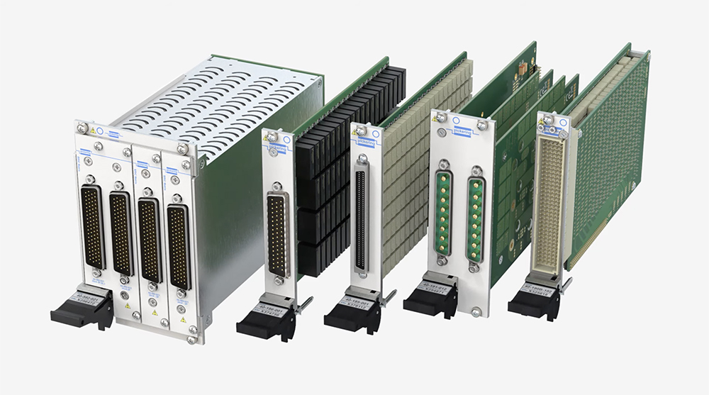
A complete physical HILS system based around the following Pickering products:

The HILS system was designed for fully automated operation, performing complete physical function tests overnight unattended. For a more specific, granular test, the EV company also specified benchtop systems based on similar products housed in Pickering’s 2-slot LXI/USB chassis (model 60-104-001). Whereas with the complete HILS system, the emphasis was on the performance, scalability, and flexibility of the Pickering solutions, small size was the key advantage for the benchtop tester.

In addition to these benefits, the EV test system development team commented that Pickering’s long history of delivering high-quality switching and simulation products that are easy to use and program were significant reasons for choosing Pickering. “With all the changes we were dealing with, it was nice to have something to rely on – that I don’t have to worry about,” said Pickering’s customer.
Learn more about Hardware-in-the-Loop testing at pickeringtest.com.
Sponsored by Pickering interfaces
[ad_2]
Source link